TOOCAA Smart Camera
Product Description
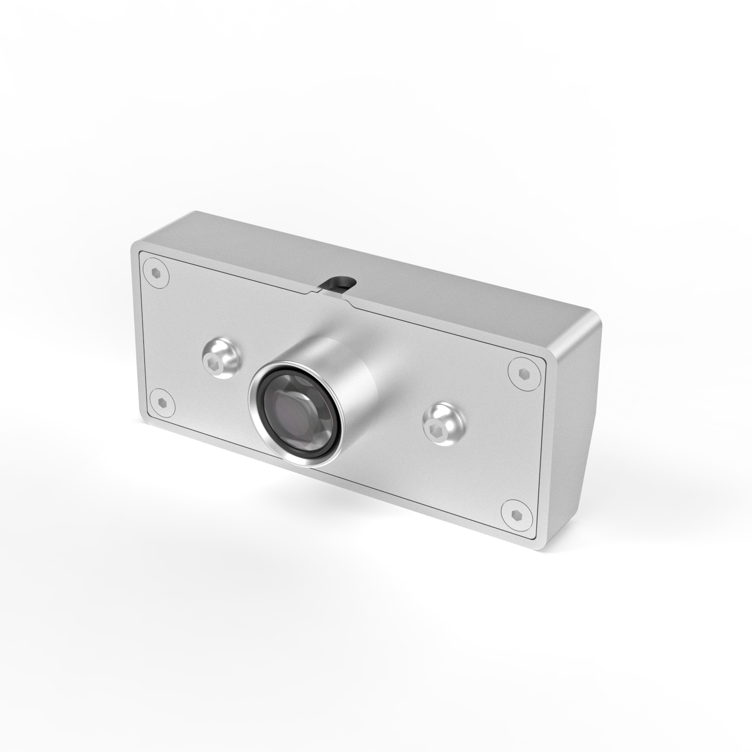
TOOCAA L2 Smart Camera helps you realize all your wonderful ideas with precise auxiliary positioning technology. TOOCAA Smart Camera for L2 achieves perfection with precision.
- 【Metal Texture】The all-metal shell design is durable and luxurious. A combination of design and technology can create something that feels futuristic.
- 【Easy Calibration】Simplify the calibration process, and select the best parameters with one click. Simple and easy to operate, greatly improving your work efficiency.
- 【Detailed to every pixel】 5 million ultra-high pixels ensure the generation of high-quality images, the 150DPI resolution can perfectly display every inconspicuous detail.
- 【Precise positioning】Millimeter-level precision positioning, no blind spot recognition of a large area of 400 mm × 400 mm, supporting the design requirements of various materials.
- 【Ready to use unboxing】The camera adopts a modular design, and uses high-precision screws to fix it to the laser-cutting machine. It can be used after the USB cable is connected to the device.
Product Specification
| Module size | 90mm × 40mm × 35mm |
| Number of pixels | 5 million pixels (2592px × 1944px) |
| Resolution | 150 DPI |
| Max dynamic range | 85 dB |
| Focal length | 30cm-infinity |
| Connection interface | USB 2.0 |
| Compatible system | Win XP, Win 7 or Linux 2.6.20 and above |
| Compatible software | LightBurn、TOOCAA Studio |
| Gross weight | 250g |
| Packaging size | 135mm × 55mm × 102mm |
Camera Installation
Step 1
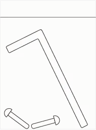
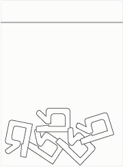
Take out the camera, screw accessories, and carabiner accessories from the packaging box.

Step 2
Remove the magnetic nameplate on the top of the laser cutting machine.

tep 3
Use the screw fittings to secure the camera to the top of the laser cutter.
 Note: Please remove the black protective cover on the camera after fixing it.

Step 4
Organize and secure your camera's wiring with the carabiner accessory.

Step 5
Connect the camera's USB cable to your computer, open LightBurn, and follow the instructions below to complete the connection. You can start using it normally.

 Note: Each time before using the camera, you need to perform a device connection and a two-step (Camera lens calibration and Camera alignment calibration) camera calibration operation.
Camera connection tutorial
For the camera to accurately assist the laser cutting machine in positioning and operation, 3 step operations are required.
- Camera lens calibration
- Camera alignment calibration
- Camera application
Please read the following camera connection tutorial and connect the camera.
Camera lens calibration
 Q&A:The lens type of TOOCAA Smart Camera for L2 is a fisheye lens. To effectively use this type of fisheye lens, it is necessary to calibrate the lens to ensure that it does not distort when capturing images.
Camera Model Selection
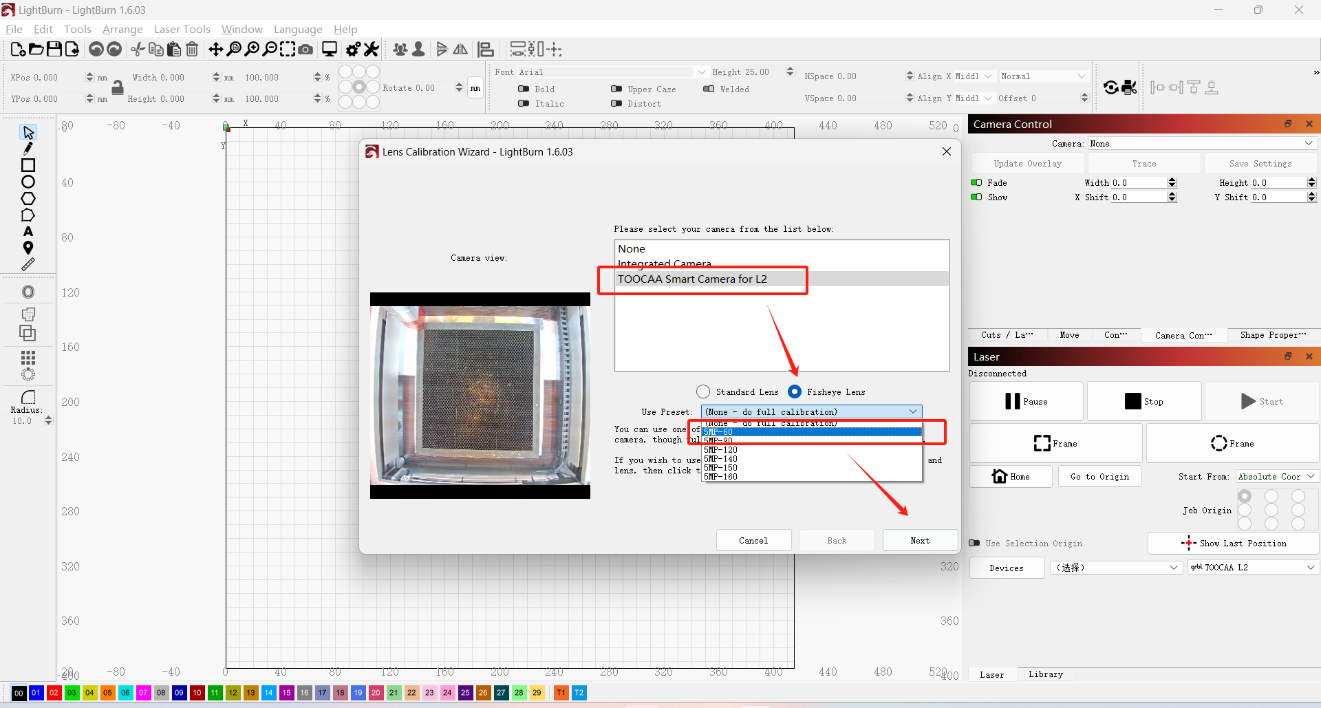
Connect the laser cutter and camera to your computer with a USB cable, start LightBurn, and click the Calibrate Camera Lens option.
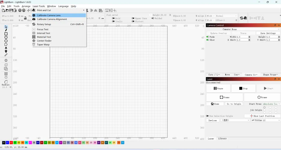
Select the camera model. Select Fisheye Lens and 5MP-60, and click Next.
 Q&A: 5MP-60 means the camera has a resolution of 5 megapixels and can record video at 60 frames per second. Just select the corresponding parameters in LightBurn.
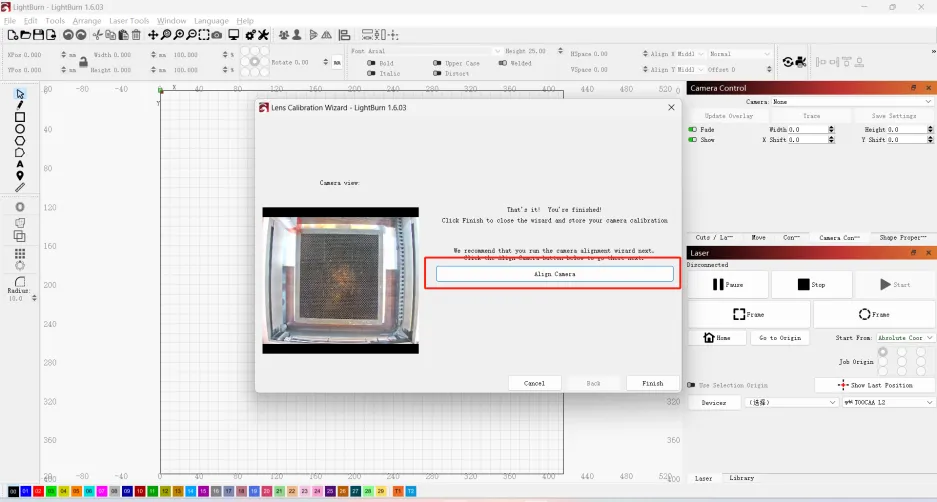
Click the Align Camera option to start camera alignment calibration.
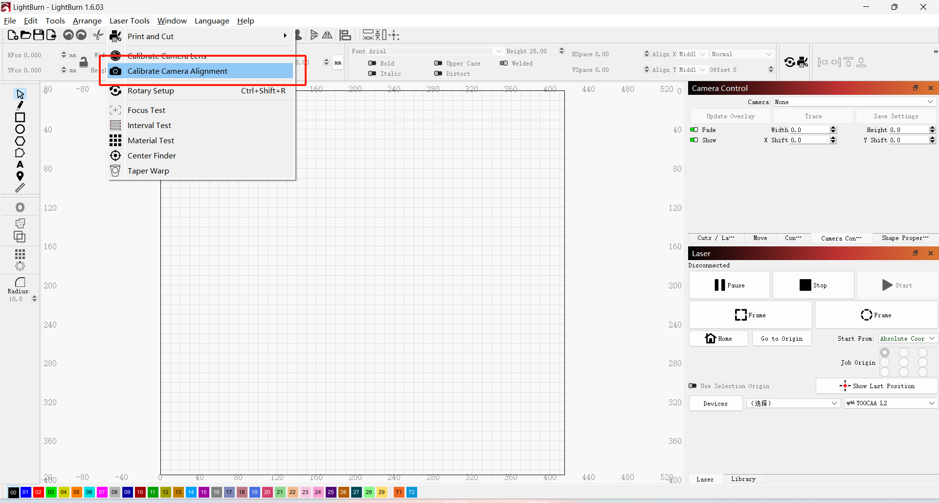
 TIPS:If you click other options by mistake, you can start camera alignment calibration through LightBurn Tools→Camera Alignment Calibration.
Camera alignment calibration
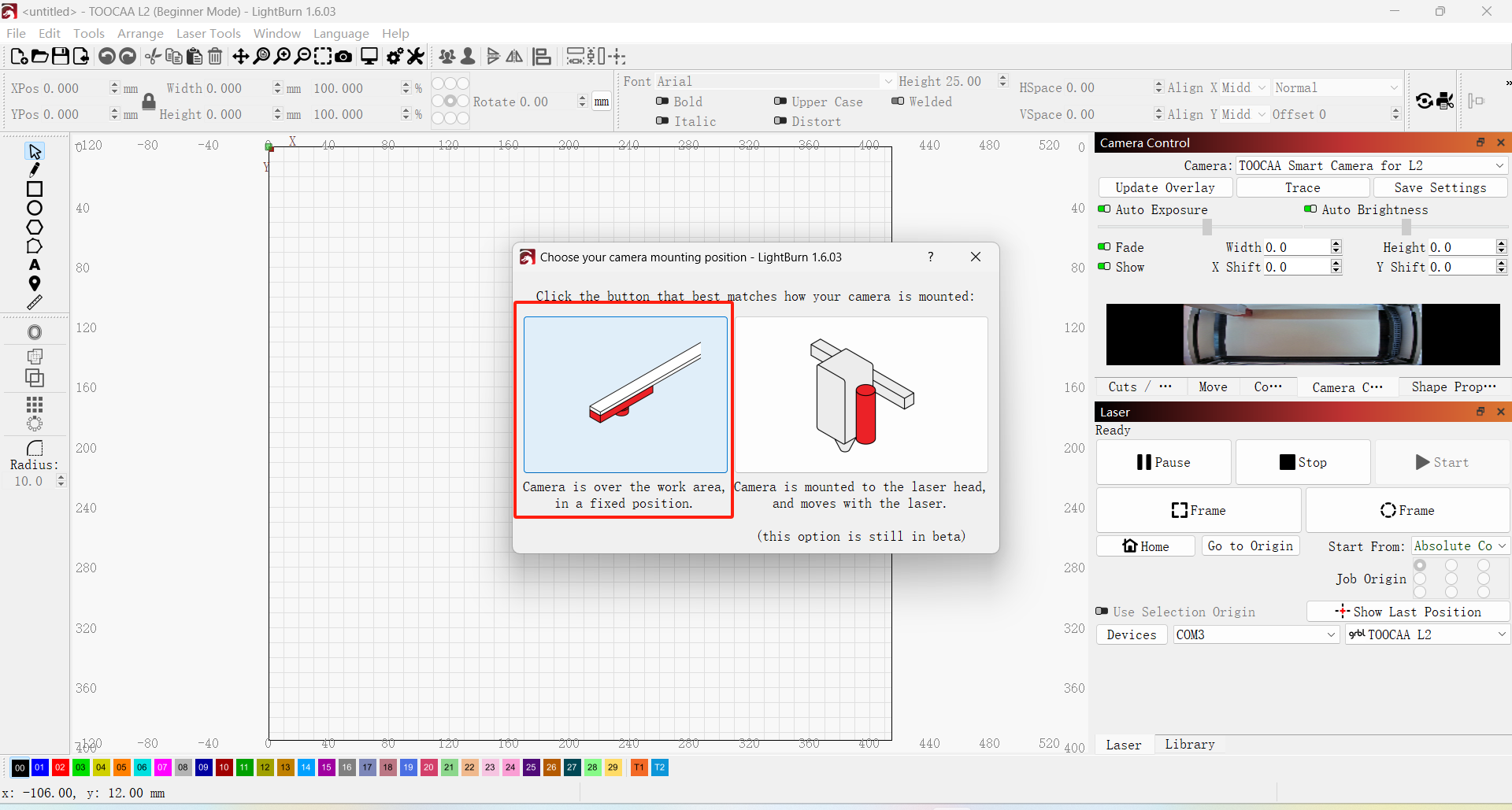
Select the connection mode
In the Connection Mode window, select the mode where the camera is located on top of the laser cutter (option 1 on the left).
Test image generation
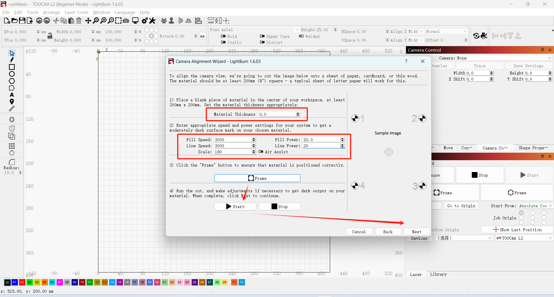
Prepare 400*400 paper or other material for test image generation. Lay the material flat on the bottom of the laser cutting machine, and adjust the corresponding parameters according to the selected material thickness. Select the engraving parameters of the appropriate material, click the Frame button to test, and then click to start engraving the test image. Click Next when the test image is engraved.
 Note: The parameters shown in the figure are for reference only. Please set the corresponding parameters according to the material and thickness of the actual test material!
 Note: If an alarm sounds, check whether the laser head has been reset. If the alarm still sounds after resetting, adjust it appropriately to reduce the proportion.
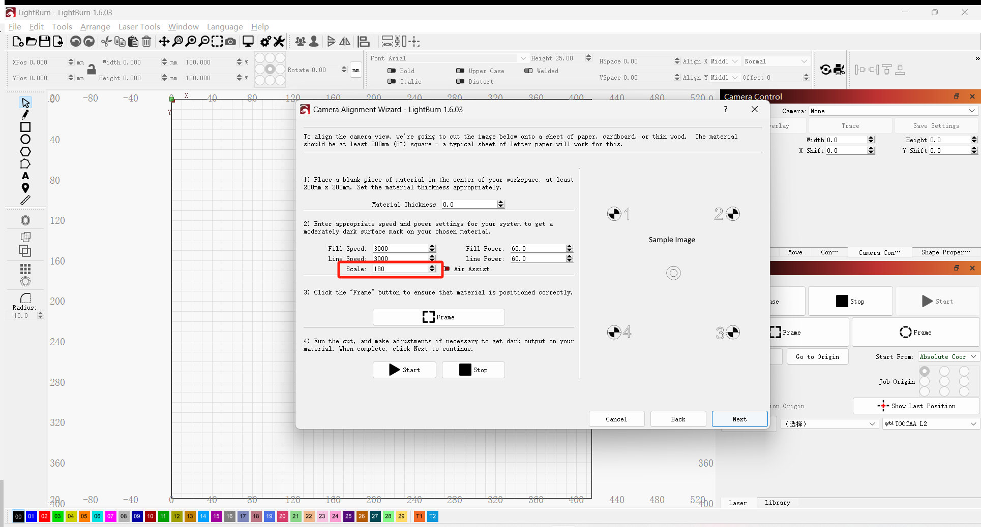
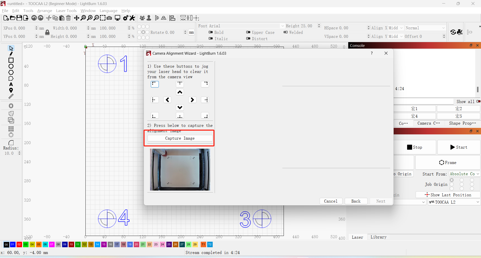
Image location capture and marking
Capture the generated test image. Proceed to the next step after the capture is completed.
 Note: The captured image should be the same as the preview perspective. If the image captured is a fisheye view, please return to the lens calibration step and re-calibrate the lens.
Use the mouse to mark and confirm the 4 positions on the test image in the order of numbers shown.
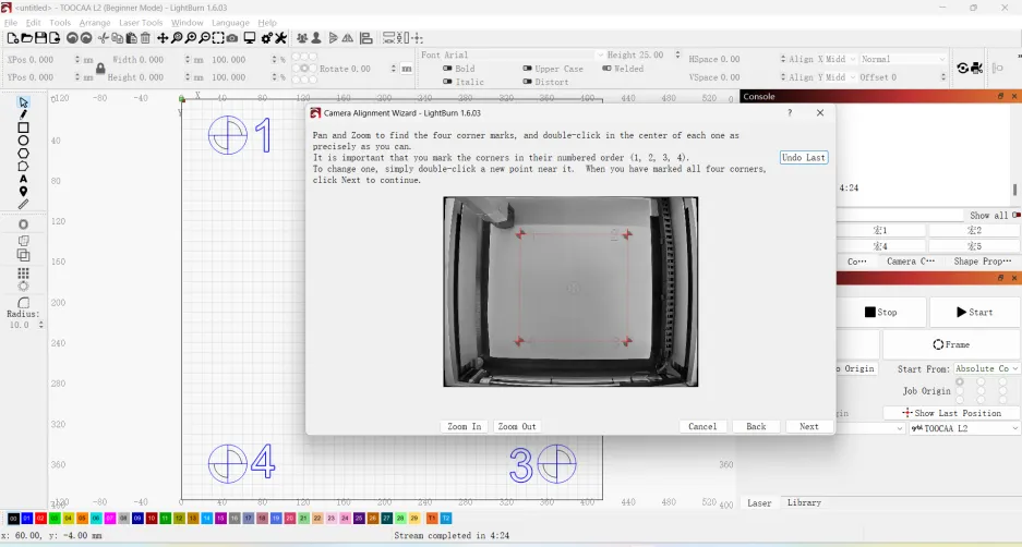
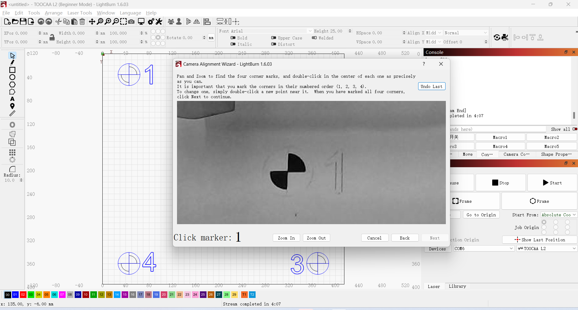
 TIPS: You can move the mouse, zoom in and out to test the image, and then accurately click the circle center at 4 locations.
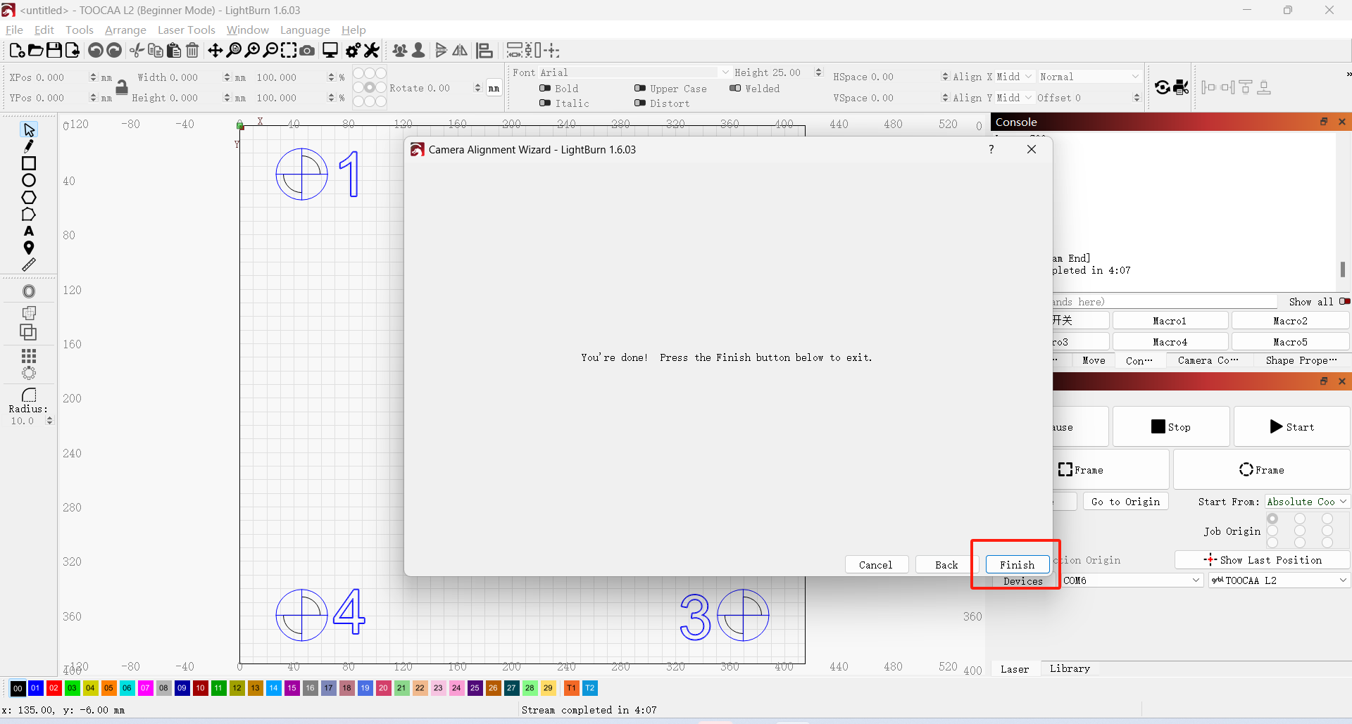
After the 4 locations are accurately marked one by one, click Finish.
Camera Application
Camera control window Overlay preview
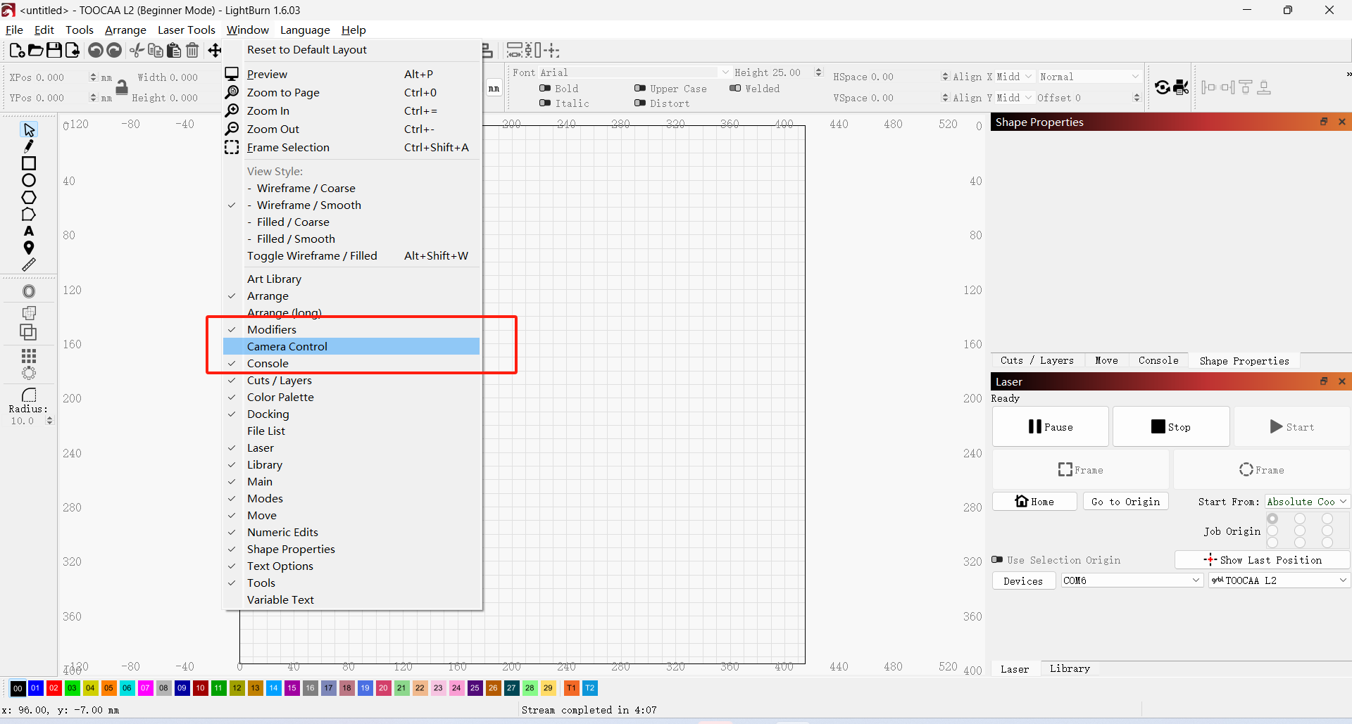
Click Window→Camera Control to open the Camera Control window.
Click Update Overlay and your calibration is complete!
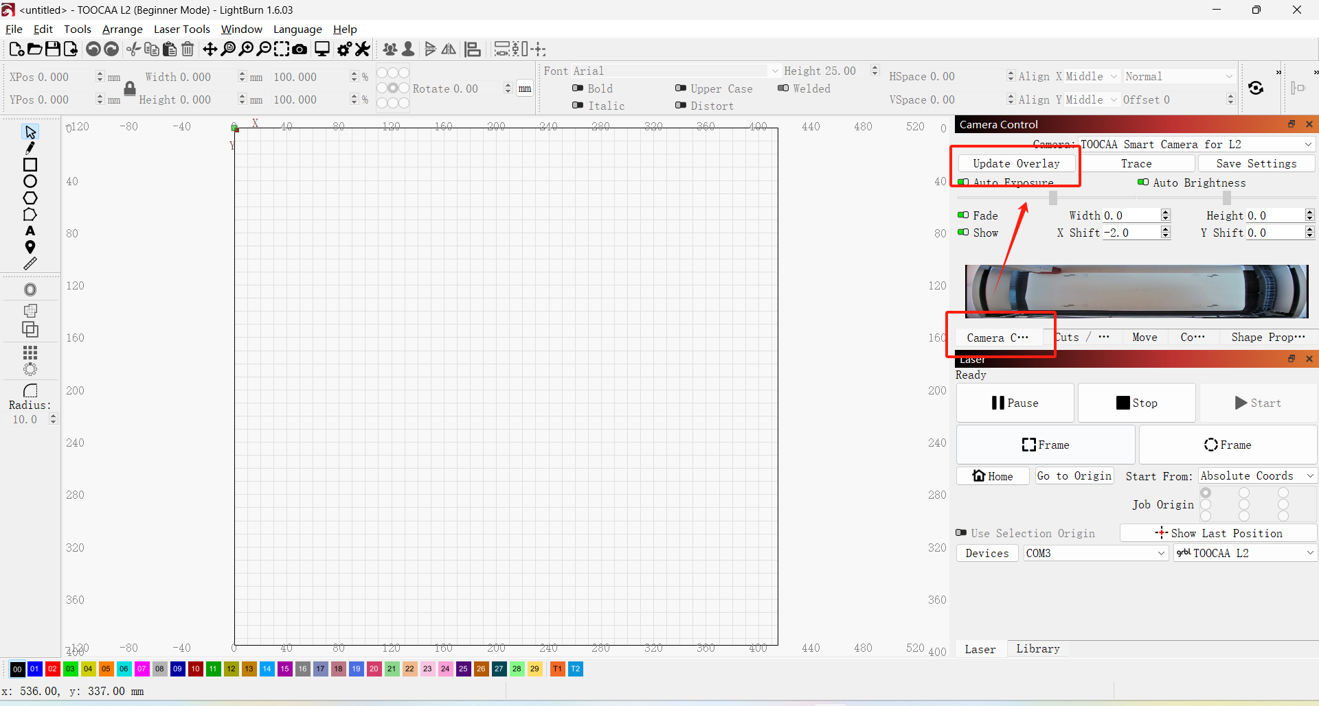
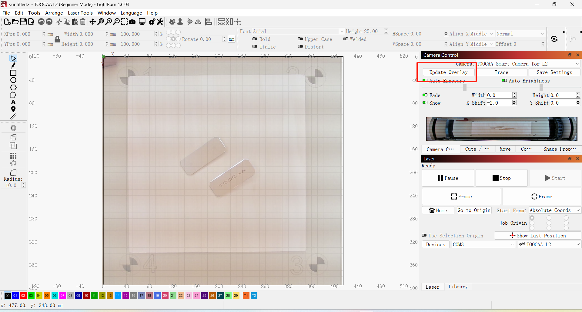
 TIPS: After adjusting the position of the material to be cut inside the laser-cutting machine, there is no need to recalibrate the camera, click Update Overlay.
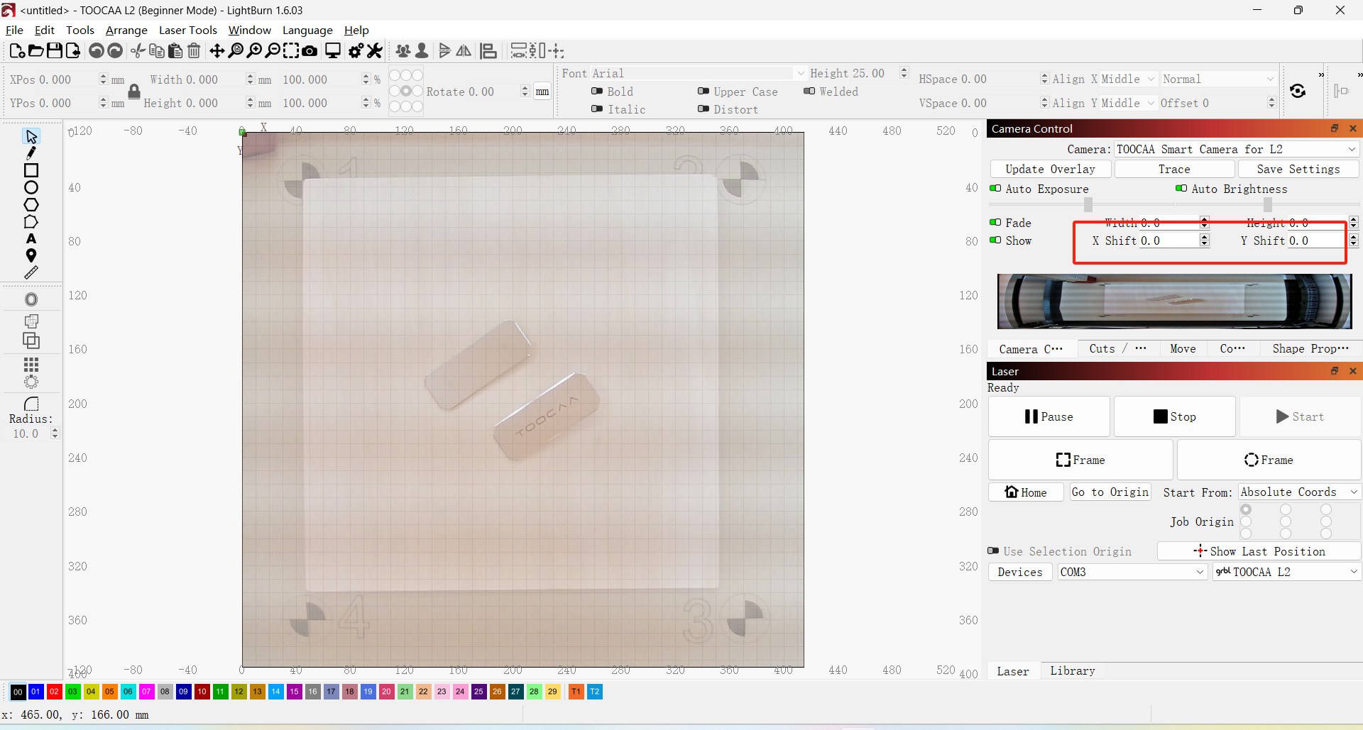
If the preview position is offset from the actual position, you can adjust the X and Y axes in the Camera Control Panel.
Practical operation and application of camera
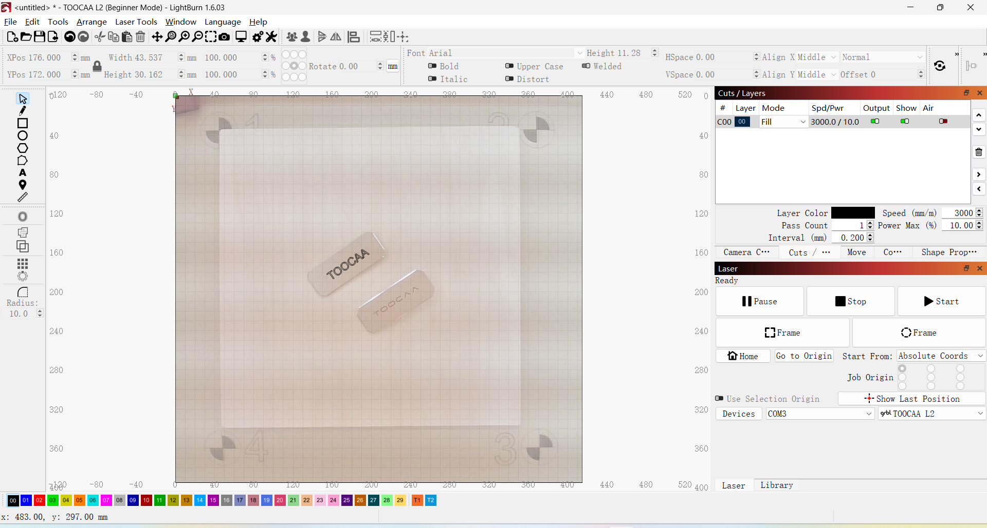
Place the cutting materials into the laser cutter and click "Update Overlay".
In the LightBurn overlay view, you can design the engraving and cutting of the material according to the target position.
 Note: Each time before using the camera, you need to perform a device connection and a two-step (Camera lens calibration and Camera alignment calibration) camera calibration operation.
Camera connection tutorial website
Camera usage tutorial website: https://docs.lightburnsoftware.com/Camera/index.html
Camera usage tutorial video website: https://www.youtube.com/watch?v=ONnmCaoUkLQ